
Fan Chief Commercial
Wireless fan control with time clock

Section 1:
Electrician’s Guide for The Fan Chief System
The Fan Chief Commercial is designed for easy installation and operation. The system is designed to control
variable frequency drives on AmeriWind fans
Main Features
The System is designed for the unique challenges of HVLS fans.
The Fan Chief System:
• Automatic control of VFD by time
• Touch screen display
• Up to 9 fans each with their own speed
• 0-10v output for analog controlled fans
• Modbus output for wireless fans

Section 2 - Programming
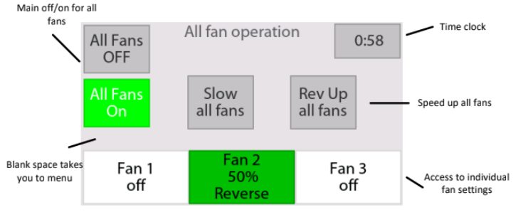
Home screen to control all fans
- Blank space takes you to menu If the All Fans OFF button is selected, no fans will run and the timers are deactivated. If the ALL Fans On button is selected, only the enabled fans will run. The timers will be able to enable or disable individual fans.
Menu
- The time parameters allow you to start and stop the fan via a weekly time clock.
- The applicable days and fans applied are selectable. Any combination of fans can start or stop automatically. If you simply want to make sure all the fans get turned off at the end of the shift, Select all the fans, and set an Off time for shortly after the shift ends Hours are on a 24 hr basis, 0:00 means disabled. There are up to 20 time periods. If there are 9 or more fans, 9 and above will mimic fan 8’s time parameters.

Time Clock for Fans
- The time parameters allow you to start and stop the fan via a weekly time clock.
- The applicable days and fans applied are selectable. Any combination of fans can start or stop automatically. If you simply want to make sure all the fans get turned off at the end of the shift, Select all the fans, and set an Off time for shortly after the shift ends Hours are on a 24 hr basis, 0:00 means disabled. There are up to 20 time periods. If there are 9 or more fans, 9 and above will mimic fan 8’s time parameters.
Parameters
- There are several parameters that you can change.
- The parameters are labeled P1, P2 .... These parameters are the temperature setpoints and values you can adjust.
Individual fan page
- Each fan has an individual screen with independent speed and direction.
Setup Menu Configuration
The Setup Menu configures the controller hardware and connected sensors. These settings are typically configured during installation and should only be changed by qualified personnel who understand the system requirements.
The Setup Menu configures the controller hardware and connected sensors. These settings are typically configured during installation and should only be changed by qualified personnel who understand the system requirements.
| Parameter ID | Description | Default | Min | Max |
|---|---|---|---|---|
| P1 | Temperature display units (Fahrenheit or Celsius) | F | — | — |
| P5 | Number of fans / zones | 1 | 1 | 9 |
| P9 | Enable external digital input. 0 = Not Used, 2 = Input 37, 3 = Input 34 | 0 | 0 | 34 |
| P11 | Cost per kW for electrical fan data calculations | 10 | 1 | 255 |
| P14 | Minimum voltage for 0–10V output when fan is operating at slow speed | 0 | 0 | 10 |
| P15 | Maximum voltage for 0–10V output when fan is operating at full speed | 10 | 0 | 10 |
| P19 | Reset controller to factory defaults. Set to 0 to reset the entire unit. Use with caution. | 3 | 0 | 3 |
Controller Specifications
Enclosure Size: Nominal 5" H × 7" W × 3" D
Input Voltage: FCT-1AC = 120–240 VAC, FCT-1 = 24 VDC
Outputs: Two Normally Open pilot-duty relays and one 0–10V control signal
Communications: Modbus Wireless
Warranty: 1 Year
Enclosure Size: Nominal 5" H × 7" W × 3" D
Input Voltage: FCT-1AC = 120–240 VAC, FCT-1 = 24 VDC
Outputs: Two Normally Open pilot-duty relays and one 0–10V control signal
Communications: Modbus Wireless
Warranty: 1 Year
Fan Hertz Scaling & Rotation Settings
The fan HZ scales each fan's 0–100% output percentage to the actual motor hertz (Hz) or operating speed. These values are typically preset before the controller is delivered. The maximum usable speed is limited by the fan itself and should not be considered unlimited.
Fan rotation can also be inverted using parameters P201 through P219.
| Parameter ID | Description | Default | Min | Max |
|---|---|---|---|---|
| P161 | Fan 1's minimum Hertz | 6 | 1 | 100 |
| P162-179 | Remaining fan's minimum Hertz | 6 | 1 | 100 |
| P181 | Fan 1's max Hertz. Hertz command at 100% speed | 18 | 1 | 255 |
| P182-199 | Remaining fan's max Hertz at 100% speed | 100% | 5% | 100% |
| P201 | Fan #1 Invert Rotation (0 = No, 1 = Yes) | 0 | 0 | 1 |
| P202-219 | Remaining Fan Direction Invert | 0 | 0 | 1 |
AmeriWind Recommended Hertz Settings (February 2022)
12 ft E Series (1 HP): Minimum 16 Hz • Maximum 52 Hz
14 ft E Series (1 HP): Minimum 10 Hz • Maximum 40 Hz
18 ft E Series (1 HP): Minimum 8.5 Hz • Maximum 24 Hz
18 ft E Series (1.5 HP): Minimum 10 Hz • Maximum 35 Hz
20 ft T Series (2 HP): Minimum 6 Hz • Maximum 22 Hz
24 ft T Series (2 HP): Minimum 6 Hz • Maximum 18 Hz
Please Note: These Hertz values are intended as general recommendations only. The Hertz-to-RPM ratio varies between motor styles and may change at any time due to design updates, manufacturing changes, or new performance data.
| Specification | Details |
|---|---|
| Enclosure Size | Nominal 5" H × 7" W × 3" D |
| Input Voltage | FCT-1AC: 120–240 VAC FCT-1: 24 VDC |
| Outputs | 2 Normally Open (NO) pilot-duty relays 1 × 0–10V control signal |
| Communications & Warranty | Modbus Wireless 1-Year Limited Warranty |
Quick Overview: Compact, rugged controller with flexible power options, wireless Modbus communication, and integrated relay and 0–10V fan control outputs.